Selecting the right check valves is a reliability decision, not a catalog exercise. A valve may fit the pipe and still fail under pulsation, reverse flow, or water hammer. The wrong choice can create noise, vibration, leakage, and costly pump damage.
MarketsandMarkets estimates that the global check valve market will grow steadily through 2028, driven by water treatment, energy, chemical processing, and expanding industrial infrastructure. Grand View Research also identifies aging pipelines and stricter process-efficiency requirements as major valve-market drivers. These figures show demand. They do not replace engineering judgment. Each installation needs a closer look.
Pressure matters. So does velocity.
Valve engineer and author Philip L. Skousen offers a practical principle: “A check valve should be selected for the service, not merely for the line size.” That advice remains relevant beside a noisy pump skid or a wastewater discharge line carrying suspended solids. Engineers should compare swing, lift, wafer, dual-plate, and axial designs against flow direction, cracking pressure, temperature, fluid chemistry, and maintenance access.
Standards provide a disciplined foundation. API 594 addresses wafer, lug, and double-flanged check valves, while ASME B16.34 covers pressure-temperature ratings and construction requirements. However, standards cannot predict every field condition. A valve that performs well in clean water may struggle with slurry or rapidly cycling air.
This guide examines how to match check valves with system behavior, not assumptions. It also questions common shortcuts, because a lower purchase price can hide higher operating risk.
A check valve allows fluid to move in one direction and blocks reverse flow. This simple action protects pumps, filters, meters, and piping. Without it, backflow can drain a line, contaminate clean fluid, or spin a pump backward. The U.S. Department of Energy reports that pumping systems may offer 20–50% energy-saving opportunities through better system design and maintenance. A poorly selected check valve can reduce those gains through pressure loss.
Start with the fluid, temperature, pressure, flow rate, and pipe orientation. Then examine cracking pressure, closing speed, body material, and maintenance access. A swing valve may suit clean, steady water service. A spring-assisted valve may respond better in vertical piping or fluctuating flow. Fast closure can reduce reverse flow, but it may also create water hammer. The Hydraulic Institute’s pump-system guidance stresses matching components to actual operating conditions, not only maximum ratings. This is where many designs become imperfect. A larger valve is not automatically safer.
Tips: Measure normal flow, not just peak flow. Check the manufacturer’s pressure-drop curve. Confirm the valve can close before reverse velocity rises. Install it with enough straight pipe and service clearance. Inspect the seat after repeated cycling. Small debris can prevent tight closure. Field conditions often differ from design sheets, so record pressure and noise during commissioning. A quiet valve is not always a healthy valve. Revisiting the selection after six months can reveal problems hidden during startup.
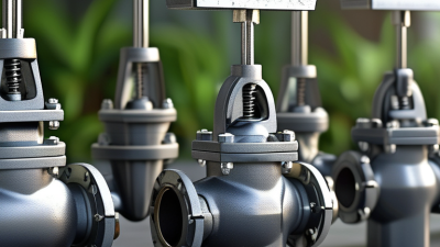
How to Choose the Right Check Valves for Your System?
Start with measured operating conditions, not nominal pipe size. Record normal, minimum, and peak flow rates. Include startup flow and possible reverse-flow events. A valve that closes too slowly may create water hammer. A valve that closes too quickly may increase pressure shock. The U.S. Department of Energy’s Improving Pumping System Performance sourcebook reports that pumping systems can consume 25–50% of energy in some industrial plants. Small pressure losses can therefore become expensive over time. Define inlet pressure, outlet pressure, differential pressure, and the required cracking pressure. Then compare these values with the valve’s tested performance.
Temperature and media chemistry need equal attention. Identify the fluid’s viscosity, density, solids content, corrosiveness, and gas presence. Water, steam, oil, and chemical solutions do not behave alike. Check the minimum and maximum temperature, including cleaning cycles and emergency conditions. Material compatibility should follow documented engineering data and recognized standards, such as ASME B16.34 and ISO 5208. Flow direction and installation position also matter. A first estimate is not enough. Real systems can surprise us.
Tips: Build a simple operating table before selecting the valve. List normal, minimum, and maximum values. Ask for verified flow-coefficient, leakage, and pressure-drop data. Do not rely only on catalog averages. If field readings are uncertain, label them clearly and allow a safety margin. Recheck the choice after commissioning, because actual flow may differ from the design model.
Define flow, pressure, temperature, and media requirements before selecting the valve type and construction material.
The chart shows representative upper service temperatures for commonly used valve body materials. Actual limits depend on pressure rating, seal material, fluid chemistry, installation orientation, and applicable standards. Confirm the final selection against the valve manufacturer's certified data.
Choosing a check valve starts with the operating conditions, not the pipe size alone. For clean liquids with steady, moderate flow, a swing check valve can offer low pressure loss. It needs enough flow velocity to close reliably. At low flow, it may chatter or remain partly open.
For vertical piping or space-limited installations, a spring-loaded lift or wafer valve may fit better. Spring force helps the disc close before reverse flow develops. This matters near pumps, especially where water hammer is possible. High-pressure gas service often requires a guided piston design, while viscous fluids may need a larger passage to reduce sticking. Fluids carrying particles require careful clearance checks. Small debris can prevent tight closure.
Temperature changes also affect seat materials, spring strength, and body expansion. Always compare the valve’s pressure rating with both normal and surge pressure. Check the actual flow direction and mounting position. I have seen otherwise suitable valves fail because installation clearance was ignored. That mistake is easy to make. A slower-closing valve may reduce shock, but it can increase reverse flow. A faster valve may protect the pump, yet create a sharp pressure spike. The best choice often depends on measured system behavior, not a catalog description. Field testing and maintenance records should influence the final selection.
Choosing a check valve begins with the fluid, not the catalog photograph. Identify temperature, pressure, viscosity, and chemical compatibility before comparing models. Stainless steel suits many clean, corrosive services, while brass may fit moderate water duties. Plastics can resist selected chemicals, but temperature limits are easy to overlook. Check the fluid’s actual composition, including cleaning agents and suspended particles. A material chart is useful. It is not infallible. Confirm data with a qualified engineer when conditions change.
Valve size should match required flow, not simply pipe diameter. A larger valve can reduce velocity, yet it may close slowly and allow reverse flow. A smaller valve can create excessive pressure loss. Review flow rate, cracking pressure, allowable loss, and expected cycling frequency. For connections, match threaded, flanged, grooved, or welded ends to the existing piping standard. Verify thread type and gasket material. Small mismatches cause large leaks. I have seen installers measure only the outside diameter, then discover incompatible threads during shutdown.
Installation orientation depends on the valve mechanism. Some spring-loaded designs work in multiple positions, while swing designs need suitable flow direction and clearance. Follow the arrow on the body and keep the disc away from nearby elbows or pumps. Support heavy piping separately. Flush debris before installation, and inspect the seat after pressure testing. A level check is worthwhile. In real projects, maintenance access is often treated as an afterthought. That decision can make a reliable valve difficult to inspect. Record the selected material, size, connection, orientation, and test results for future technicians.
| Check Valve Type | Typical Applications | Common Body Materials | Recommended Sizing Considerations | Connection Options | Preferred Installation Orientation | Key Selection Notes |
|---|---|---|---|---|---|---|
| Swing Check Valve | Water distribution, wastewater, fire-protection piping, and low-to-moderate velocity liquid service | Ductile iron, carbon steel, stainless steel, or bronze | Select the line size only when the valve provides acceptable pressure loss; avoid excessive flow velocity that can cause disc slam | Flanged, wafer, grooved, threaded, or socket-welded designs | Horizontal flow is generally preferred; many designs permit upward vertical flow, but the manufacturer’s flow-direction mark must be followed | Simple and economical, but may be unsuitable where reverse-flow shock or water hammer is a major concern |
| Spring-Loaded Inline Check Valve | Pump discharge, compressed-air systems, chemical lines, and applications requiring fast closure | Stainless steel, carbon steel, bronze, engineered plastics, or corrosion-resistant alloys | Check cracking pressure, maximum flow, pressure drop, and the valve’s flow coefficient; undersizing increases energy loss | Threaded, socket-welded, butt-welded, or flanged | Can often be installed in horizontal or vertical lines when the flow direction agrees with the arrow | Spring-assisted closure can reduce reverse flow, but the spring adds pressure loss and requires material compatibility |
| Lift Check Valve | Clean liquids, steam, gas, and high-pressure process piping | Carbon steel, stainless steel, alloy steel, or bronze | Requires sufficient differential pressure to lift the disc; verify flow capacity and pressure-drop data at the operating rate | Threaded, socket-welded, butt-welded, or flanged | Usually installed in horizontal piping; vertical installation is generally limited to upward flow unless specifically approved | Provides reliable shutoff in clean service but is more sensitive to dirt, solids, and incorrect orientation |
| Dual-Plate Wafer Check Valve | Large-diameter water, HVAC, industrial, and process pipelines where compact length is important | Ductile iron, carbon steel, stainless steel, or nickel-aluminum bronze | Confirm minimum operating velocity, pressure class, disc spring rating, and flange compatibility; do not assume the wafer body replaces a flange gasket | Wafer or lug-style installation between flanges | Often suitable for horizontal and vertical upward flow; keep clearances from pumps, elbows, and reducers according to installation requirements | Short face-to-face length and low weight; correct centering between flanges is essential |
| Ball Check Valve | Wastewater, slurry-containing liquids, viscous fluids, and low-pressure drainage systems | Cast iron, ductile iron, stainless steel, PVC, CPVC, or lined metal | Verify solids passage, ball travel, pressure drop, and minimum flow needed to move the ball from the seat | Threaded, flanged, solvent-cement, or union connections depending on body material | Typically installed with flow upward or horizontally; follow the arrow and keep the valve accessible for cleaning | Good resistance to clogging in solids-bearing service, but not normally selected for precise, low-loss flow control |
| Foot Valve with Strainer | Pump suction lines, wells, tanks, irrigation, and systems requiring liquid-column retention | Bronze, stainless steel, PVC, or other materials compatible with the pumped fluid | Size for the pump suction requirement and acceptable inlet velocity; account for strainer pressure loss and available submergence | Threaded, flanged, solvent-cement, or union connections | Installed vertically at the end of the suction pipe and kept submerged below the minimum liquid level | The strainer must remain clean; excessive suction loss can contribute to pump cavitation |
| Piston Check Valve | High-pressure liquid, steam, gas, and process systems requiring controlled closing behavior | Carbon steel, stainless steel, alloy steel, or bronze with suitable seat materials | Confirm pressure class, temperature rating, flow coefficient, cracking pressure, and resistance to wear at the expected cycle frequency | Threaded, socket-welded, butt-welded, or flanged | Normally horizontal, unless the specific design is rated for vertical flow | Suitable for demanding service, but requires clean operation and correct lubrication or maintenance where applicable |
| Selection Dimension | What to Verify Before Ordering | Practical Guidance |
|---|---|---|
| Fluid Compatibility | Fluid composition, concentration, pH, suspended solids, viscosity, and cleanliness | Select body, disc, spring, ball, shaft, and seat materials as a complete wetted-material combination |
| Pressure and Temperature | Maximum operating pressure, design pressure, minimum and maximum temperature, and pressure transients | Use the valve’s pressure-temperature rating; do not base selection on nominal pipe size alone |
| Flow Performance | Normal, minimum, and maximum flow rate; allowable pressure drop; risk of water hammer | Compare published pressure-loss data at actual flow conditions and avoid operating continuously near the valve’s unstable low-flow range |
| Nominal Size and Rating | Pipe inside diameter, pressure class, flange standard, wall thickness, and available installation space | Match the valve connection dimensions and pressure rating to the piping system; reducers may be required when process velocity differs from line size |
| Installation Orientation | Flow arrow, permissible horizontal or vertical position, nearby elbows, pumps, reducers, and maintenance access | Install in the approved direction and provide straight-run or anti-turbulence clearance when required by the valve design |
| Connection and Maintenance | Threaded, flanged, wafer, grooved, welded, or plastic joining method; replacement access and isolation points | Choose a connection that matches the piping standard and allows inspection, cleaning, repair, or replacement without unnecessary shutdown time |
Note: Final valve selection should be confirmed against the applicable piping code, pressure-temperature rating, flow calculations, material compatibility data, and the manufacturer’s installation instructions.
Choosing the right check valve starts with evidence, not catalog images. Verify flow direction, cracking pressure, and shutoff performance under actual operating conditions. A valve that works on a clean test bench may behave differently with hot fluid, suspended solids, or pulsing pressure. Request pressure-drop curves and material certificates from qualified suppliers. Compare them with your design calculations. Check installation orientation, pipe size, connection type, and available space before approval. Small mismatches can create major service problems.
Performance verification should include repeated cycling, leakage checks, and response at minimum flow. Record inlet and outlet pressures with calibrated gauges. Listen for chatter, vibration, or sudden water hammer. These signs often appear before visible damage. Test the valve after temperature changes, because seals and springs may respond differently when cold. I have seen teams accept one low-leakage result, then overlook unstable cycling performance. That shortcut deserves a second review. Real systems are rarely as calm as laboratory rigs.
Tips: Match wetted materials with the fluid, temperature, and cleaning chemicals. Confirm spare seals and inspection intervals before installation. Keep access for removal; a compact valve is not always maintainable. Check whether it tolerates reverse pressure and occasional dry operation. Document baseline readings, torque settings, and the installation date. Inspect upstream strainers when debris is possible. Maintenance plans should reflect actual duty, not only general guidance. Leave room for judgment. Field conditions can expose assumptions that paperwork misses.
Same Day Shipping
ISO Certified Production