Choosing the right ball check valve starts with the fluid, not the catalog photo. Is the line carrying clean water, wastewater, or a slurry with grit? Check the flow rate, pressure range, temperature, pipe orientation, and available installation space. These details help determine whether a ball valve can move freely and seat reliably. Small details matter.
The U.S. Department of Energy’s Improving Pumping System Performance sourcebook reports that pumping systems account for nearly 20% of global electricity use. That figure is a reminder to consider the whole system, not just the valve’s purchase price. An unsuitable valve can contribute to pressure loss, noise, or repeated maintenance. For selection guidance, Robert Anderson, author of The Practical Guide to Check Valves, emphasizes matching the valve to actual operating conditions. Paraphrased: choose for the system, not merely the pipe size.
A practical review should compare body and ball materials, connection type, pressure rating, and the manufacturer’s published flow data. Ask how the ball behaves at low flow, and whether solids could prevent a tight seal. A compact valve may fit neatly between two flanges yet still be wrong for a line with frequent starts and stops. That trade-off is easy to miss. No single model suits every installation, and published performance data may not capture every field condition. Verify the selection with the supplier or a qualified engineer before specifying a ball check valve.
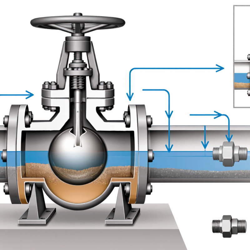
Ball check valve selection starts with the service conditions, not just the pipe size. Describe the fluid during startup, normal operation, and shutdown. Clean water behaves differently from slurry carrying sand or fibrous debris. Solids can lodge between the ball and seat, preventing a tight seal. Record particle size, concentration, and whether deposits harden during pauses. Check chemical compatibility with the valve body, ball, and seat. Temperature matters: hot fluid may soften elastomers, while cold conditions can reduce flexibility. Pressure and viscosity also influence ball movement and closure.
Tips: Note normal and extreme temperatures, solids content, and cycle frequency. Include brief starts, frequent stops, and long idle periods. Not always obvious. Consider whether the valve must seal after every shutdown or only limit backflow. A larger valve is not automatically safer; low flow may leave the ball moving weakly or seating inconsistently.
Describe the operating cycle realistically. Continuous service creates different wear from dozens of cycles per hour. Mention water hammer, pump ramp-up, and dry-start risks. If conditions vary by season, assess the full range rather than a convenient average. Site measurements are rarely perfect, but even approximate data beat guesses. Verify uncertain solids or temperature information before choosing a valve.
| Service Condition | Typical Fluid and Solids | Temperature Considerations | Operating Cycle | Selection Considerations |
|---|---|---|---|---|
| Clean water transfer | Municipal or process water with little or no suspended debris | Often near ambient temperature; confirm the valve body's and ball's allowable range for the actual minimum and maximum temperatures. | Frequent starts and stops may occur in pump discharge service. | Check pressure rating, connection size, installation orientation, and cracking pressure. Match body and ball materials to water chemistry and any treatment chemicals. |
| Wastewater and drainage | Wastewater containing suspended solids, fibers, or occasional debris | Record normal and upset temperatures; warmer wastewater can affect elastomers and other nonmetallic components. | Intermittent pumping, with possible periods of stagnation. | Consider a passage that is less prone to clogging, suitable solids-handling capability, and access for cleaning. Verify that the expected particle size and concentration are within the valve's design limits. |
| Slurry or abrasive service | Liquid carrying sand, mineral particles, or other abrasive solids | Include process temperature and temperature changes during cleaning or shutdown. | May involve continuous flow followed by flushing or shutdown cycles. | Assess erosion at the seat and ball, solids settling during downtime, and the need for wear-resistant materials. Obtain the valve's solids-size and solids-concentration limits before specifying it. |
| Viscous liquids | Thick process liquids, oils, or liquids that become more viscous at low temperature | Viscosity can rise significantly as temperature falls; evaluate startup conditions as well as normal operating temperature. | Long idle periods may be followed by startup under cold or stagnant conditions. | Check that the available differential pressure can move the ball and open the valve. Review pressure drop, ball travel, and the possibility of deposits or congealing. |
| Clean compressed air or gas | Filtered gas with low moisture and minimal particulate contamination | Account for gas temperature and possible cooling or heating during compression, expansion, and cycling. | Can be rapid or frequent, depending on the system. | Confirm the valve is suitable for gas service, including leakage expectations, pressure rating, and response at the available differential pressure. Check for seat wear or noise in high-cycle applications. |
| Corrosive process liquid | Acidic, alkaline, saline, or chemically treated liquid; solids may or may not be present | Evaluate chemical compatibility at the full operating temperature range, not just at room temperature. | Consider both steady operation and repeated cleaning, flushing, or chemical changeover. | Check compatibility of every wetted part, including the body, ball, seat, seals, and fasteners. Confirm concentration, contaminants, and cleaning chemicals with a materials compatibility reference or qualified supplier. |
| Thermal cycling service | Liquid or gas experiencing repeated heating and cooling | Specify minimum, normal, and maximum temperatures, including short-duration excursions. | Repeated thermal cycles can occur during batch processing, cleaning, or seasonal operation. | Verify that materials and seals tolerate the temperature range and cycling rate. Check for changes in clearances, seal performance, and pressure rating at temperature. |
| Intermittent pump discharge | Water or process liquid, with solids content determined by the application | Use the fluid's actual temperature range, including conditions during startup and shutdown. | Repeated pump starts and stops; reverse flow may develop when the pump stops. | Review closing behavior, reverse-flow prevention, water-hammer risk, and pressure transients. Confirm that the valve is sized for the flow rate and pump conditions rather than selected by pipe size alone. |
Specification note: Temperature limits, pressure ratings, cracking pressure, allowable solids size, and material compatibility vary by valve design and construction. Treat the examples above as screening guidance and confirm all limits against the selected valve's technical data and the actual process conditions.

Copyright © 2011-2025 Davis Valve.
All Rights Reserved.


Same Day Shipping
ISO Certified Production