Hydraulic Piston Seals may look like small components, but they control leakage, pressure retention, and smooth cylinder movement. A poor choice can leave oil on the workshop floor, score a piston, or stop a machine during a demanding shift. The right seal depends on more than its diameter. Pressure, temperature, fluid compatibility, speed, and installation conditions all matter.
A composite industry voice, hydraulic sealing specialist Alex Morgan, offers this illustrative principle: “A seal succeeds when its material, groove, and operating conditions work together.” This is an editorially created quotation, not a sourced statement from a real expert. Still, the principle reflects a practical lesson: even a premium seal can fail in a worn groove or with an incompatible fluid. Small details matter.
This guide presents 10 tips for choosing Hydraulic Piston Seals with those real-world conditions in mind. It covers seal materials, profile selection, operating limits, surface finish, and installation checks. A careful review of the equipment manual and supplier specifications can prevent costly guesswork. Yet specifications do not tell the whole story. Existing wear, temperature swings, and unexpected pressure spikes may complicate the choice. That is the catch. Use the tips as a structured starting point, then confirm critical selections with a qualified seal supplier or hydraulic engineer. A little uncertainty is worth acknowledging; the wrong assumption can be expensive.
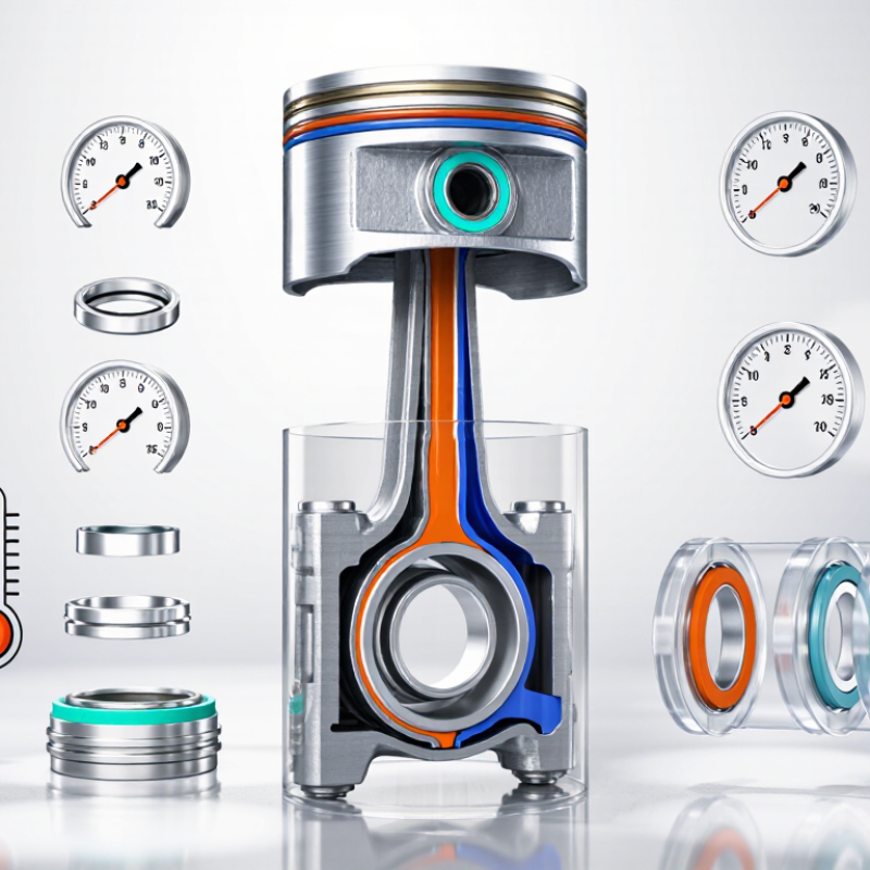
Define the full duty before choosing a hydraulic piston seal. A peak pressure of 35 MPa equals 350 bar. ISO 6022:2018 specifies a 25 MPa nominal-pressure series for hydraulic cylinders, making 35 MPa a useful warning to check the cylinder, seal clearance, and extrusion risk together. That comparison is a screening point, not a seal failure threshold. Record pressure spikes during startup, reversal, and impact—not just steady pressure. ISO 10771-1:2015 describes fatigue testing for pressure-containing components, a reminder that repeated cycles deserve attention. Static ratings alone can mislead.
Measure loaded piston speed, stroke length, cycle frequency, and dwell time. For example, a 0.5 m stroke at 0.2 m/s takes 2.5 seconds in one direction. Faster travel can increase frictional heating; long strokes also expose the seal to more sliding distance. Small detail. It matters. Note fluid temperature at the seal, including cold starts and heat after repeated cycles. Then check the proposed seal’s limits against the actual fluid, surface finish, and extrusion gap. Real machines rarely match a neat test bench. Leave margin for the duty you measured, and revisit assumptions when field temperatures or pressure peaks differ.
| 10 Tips for Choosing Hydraulic Piston Seals — Define Operating Duty: Pressure up to 35 MPa, Speed, Stroke, and Temperature | |||
|---|---|---|---|
| Operating Dimension | Example Duty | What to Specify | Seal Selection and Design Check |
| Maximum pressure | Up to 35 MPa (350 bar) | Peak and continuous pressure, pressure spikes, and whether pressure acts in one or both directions | Confirm the seal profile, material, and extrusion-gap limits at the maximum pressure. Check the gland and piston dimensions against the seal supplier’s design data. |
| Operating speed | 0.1–0.5 m/s as an example reciprocating range | Average and peak speed, direction changes, and time spent at each speed | Check friction, heat generation, lubrication, and wear at the actual pressure and speed combination. Do not assess speed as an independent limit. |
| Stroke length | 500 mm per working stroke as an example duty | Full stroke, stroke frequency, dwell time, and total daily operating time | Long or frequent strokes can increase frictional heat and wear. Evaluate the complete motion cycle and ensure the seal remains lubricated throughout travel. |
| Fluid temperature | 20–80°C operating range; record any short-duration peaks | Minimum start-up temperature, normal fluid temperature, and maximum peak temperature | Choose an elastomer or thermoplastic compatible with both the fluid and the full temperature range. Temperature capability depends on the specific compound and seal design. |
| Hydraulic fluid | For example, mineral-oil-based hydraulic fluid | Fluid type, additives, water content, and any change of fluid during service | Verify material compatibility with the exact fluid. Fluids such as water-glycol or phosphate ester may require different seal materials. |
| Extrusion gap and clearance | Measure the maximum clearance at operating pressure and temperature | Piston-to-bore clearance, tolerance stack-up, side loading, and housing deflection | High pressure can force seal material into an excessive gap. Confirm extrusion resistance and consider a suitable backup ring when the design requires one. |
| Surface finish and alignment | Use the cylinder and piston finish specified for the selected seal profile | Surface roughness, lead, scratches, bore roundness, and rod or piston alignment | Finish requirements vary by seal material and profile. Check the seal manufacturer’s surface-finish guidance and inspect for damage that could create a leak path. |
| Duty-cycle validation | Example: repeated extension and retraction under changing load | Pressure, speed, stroke, temperature, and cycle frequency together | Validate the combined duty in the intended cylinder or a representative test setup. A seal suitable for each individual condition may not suit their combined effects. |

Copyright © 2011-2025 Davis Valve.
All Rights Reserved.


Same Day Shipping
ISO Certified Production