Choosing the right Face Mechanical Seal is a reliability decision, not a catalog exercise. The seal must match the pump, fluid, pressure, temperature, speed, and operating pattern. A mismatch can lead to leakage, premature wear, or repeated maintenance. Small details matter: abrasive particles in a slurry, dry-running during startup, or a sudden temperature rise can change seal performance.
The International Energy Agency’s report, Energy-Efficiency Policy Opportunities for Electric Motor-Driven Systems, estimates that motor-driven systems use about 45% of global electricity. That figure does not measure seal-related losses. It does show why dependable rotating equipment matters across industry. A seal that supports stable pump operation can help avoid unplanned stoppages, though seal selection alone cannot guarantee energy savings. The full system deserves attention.
For engineering guidance, API Standard 682 and ISO 21049 address sealing systems for centrifugal and rotary pumps. They provide useful frameworks for defining seal arrangements and service conditions; they do not replace application-specific review. Start with the actual process data, including fluid properties, solids content, and startup frequency. Then consider materials, flush plans, installation conditions, and maintenance capability. Ask the pump or seal supplier to confirm assumptions in writing. It sounds obvious. It is often missed.
This guide explains how to choose a Face Mechanical Seal with those practical constraints in view. Some operating data may be incomplete, and that uncertainty should be acknowledged rather than guessed away. A careful selection begins with evidence, not the lowest purchase price.
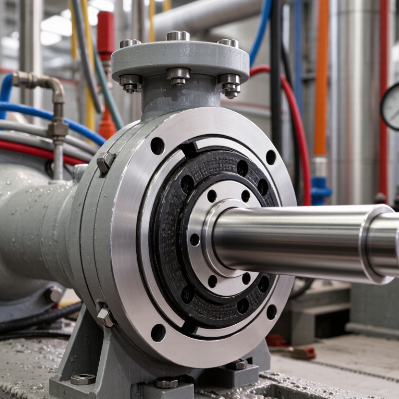
A face mechanical seal controls leakage where a rotating shaft meets stationary equipment. One face turns with the shaft; the other remains fixed. Springs and fluid pressure keep their finely lapped surfaces close together. A microscopic liquid film usually separates them, reducing friction while limiting leakage. The film also carries away heat. When it disappears, even briefly, friction and temperature can rise quickly. Small details matter.
Tips: Check the fluid, pressure, temperature, shaft speed, and startup conditions before choosing a seal. Confirm that the equipment can provide suitable lubrication and cooling. Dry running can damage faces fast.
Seal faces may use different materials because fluids vary in abrasiveness, chemical behavior, and lubricity. A seal suited to clean water may not perform well with a gritty process fluid. Installation matters too: misalignment, damaged faces, or uneven tightening can cause early leakage. Selection charts are useful, but they cannot capture every operating condition. That part deserves a second look. Record actual operating temperatures and leakage observations after startup; those details can reveal whether the chosen arrangement fits the service.
| Selection dimension | Design or option | Operating principle | Typical fit | Key checks and trade-offs |
|---|---|---|---|---|
| Seal arrangement | Single seal | One pair of rotating and stationary faces forms the primary leakage-control interface. A thin fluid film between the faces provides lubrication and removes heat. | Common, relatively simple choice for compatible, clean or mildly contaminated fluids where limited leakage to the surroundings is acceptable. | Check fluid lubricity, volatility, toxicity, emissions rules, temperature, pressure, and whether a suitable flush or cooling arrangement is available. It is not inherently leak-free. |
| Seal arrangement | Dual pressurized seal | Two seal pairs enclose a barrier fluid maintained at a pressure higher than the sealed process fluid. Barrier fluid tends to leak inward across the inner faces. | Useful when process leakage to the atmosphere must be minimized, or the process fluid is hazardous, poorly lubricating, or difficult to contain. | Requires a compatible, clean barrier fluid and a pressurized support system with monitoring. Confirm that inward barrier-fluid leakage will not contaminate or disrupt the process. |
| Seal arrangement | Dual unpressurized (tandem) seal | Two seal pairs operate with a buffer fluid between them. The buffer space is normally maintained at a pressure below the process pressure. | Can provide secondary containment and collect or monitor leakage where a pressurized barrier system is not required. | The primary seal remains responsible for containing process pressure. Define buffer-fluid handling and monitoring, and assess whether process leakage into the buffer is acceptable. |
| Hydraulic loading | Balanced seal | The geometry reduces the hydraulic closing force acting on the seal faces. The faces still need a controlled closing load to maintain contact and a lubricating film. | Often considered for higher pressure service, lower heat generation, or applications where face wear from excessive closing force is a concern. | Confirm the balance design against actual operating and transient pressures. Suitability depends on the seal geometry, materials, shaft movement, and equipment limits. |
| Hydraulic loading | Unbalanced seal | Process pressure acts over a larger effective area, contributing more hydraulic force that pushes the faces together. | May suit lower-pressure duties with compatible fluids and stable operating conditions. | Higher face loading can increase frictional heat and wear. Check pressure limits, start-up and shutdown conditions, and the risk of face distortion or inadequate lubrication. |
| Face material pairing | Carbon-graphite against ceramic or silicon carbide | A relatively compliant carbon face runs against a harder mating face. The pairing is commonly used to balance conformability, wear resistance, and running behavior. | A common starting point for many clean, lubricating liquids when the fluid and temperature are compatible with the selected grades. | Carbon grades differ in resin or impregnant and chemical resistance. Check dry-running risk, abrasives, fluid chemistry, thermal shock, and the exact ceramic or carbide grade. |
| Face material pairing | Silicon carbide against silicon carbide | Hard, wear-resistant faces run against one another. The arrangement can resist abrasive wear, but still relies on correct lubrication, alignment, and face loading. | Often considered for abrasive or corrosive services when the specific material grades are chemically suitable. | Hard faces can be vulnerable to damage from impact, misalignment, or poor lubrication. Verify chemistry, solids characteristics, cooling, and start-up conditions. |
| Secondary sealing element | Elastomer O-ring | An elastomer seals between components that do not form the primary rotating face interface. It may move axially with the seal design and can be affected by friction or deposits. | Suitable when the chosen elastomer is compatible with the process fluid and operating conditions. | Check chemical compatibility, temperature, swelling, compression set, and resistance to rapid gas decompression where relevant. Select the elastomer by grade, not generic material name alone. |
| Seal construction | Cartridge seal | Seal components are assembled and set as a unit before installation, helping preserve working dimensions and reducing the amount of adjustment required on the equipment. | Helpful where installation repeatability, maintenance time, or reduced assembly error is important. | Confirm shaft and chamber dimensions, connection requirements, available installation space, and compatibility with the equipment and seal support system. |
| Operating environment | Flush, cooling, or barrier-fluid support | A controlled auxiliary flow or fluid system helps manage heat, remove solids, maintain lubrication, or separate the process from the atmosphere. | Consider when the process fluid is hot, dirty, volatile, poorly lubricating, or otherwise difficult for the seal faces to handle directly. | Choose the arrangement based on process conditions and the required containment objective. Verify flow, pressure, fluid compatibility, instrumentation, and the consequences of support-system failure. |
Selection note: Mechanical-seal pressure, temperature, speed, and material limits depend on the complete seal design, equipment, fluid, and support arrangement. Confirm allowable operating limits and applicable requirements for the specific application before selection.

Copyright © 2011-2025 Davis Valve.
All Rights Reserved.


Same Day Shipping
ISO Certified Production