Reliable grounding begins with a component that can endure both electrical demand and harsh soil conditions. This guide examines the 7 Best Carbide Ground Rods for Reliable Grounding, focusing on durability, conductivity, installation practicality, and long-term value. A Carbide Ground Rod can offer a hardened surface that resists wear during driving, especially in compacted soil or gravelly areas.
Choosing the right rod requires more than reading product specifications. Diameter, length, coating quality, soil moisture, and connection hardware all affect grounding performance. A rod may appear strong in a product photo, yet installation can reveal weaknesses. Bent tips, damaged coatings, or poor clamps can reduce confidence quickly. Small details matter.
This comparison considers practical features that experienced installers inspect before committing to a product. We look at material consistency, corrosion resistance, driving strength, and compatibility with approved grounding systems. Installation conditions also deserve attention, because dry soil may produce different results from damp, conductive ground. No single rod fits every project. That is worth remembering.
The selected options are presented for informed evaluation, not blind replacement of local engineering guidance. Verify measurements, manufacturer instructions, and applicable electrical requirements before installation. A reliable grounding system depends on the complete assembly, including conductors, connectors, soil contact, and testing. The rod is important, but it is not the entire answer. Expect trade-offs, and inspect every connection carefully.
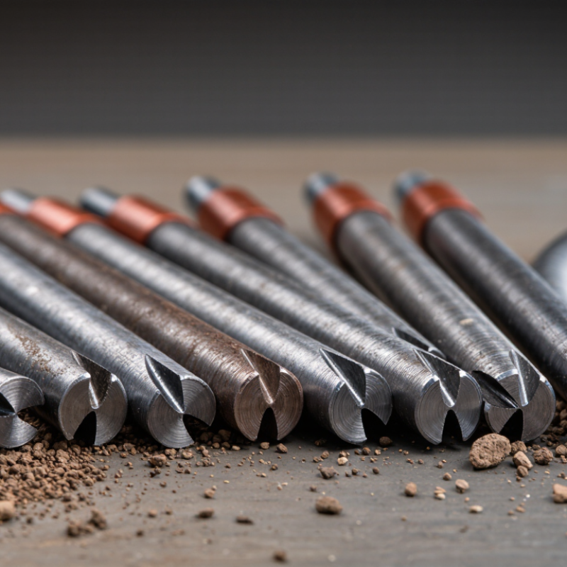
Carbide ground rods are grounding electrodes designed for difficult soil conditions. Most use a steel core with a corrosion-resistant coating and a carbide-enhanced driving tip. The tip helps the rod penetrate compact clay, gravel, or weathered rock without deforming quickly. It does not make the entire grounding system automatically reliable.
The rod works by creating a conductive path from electrical equipment into the earth. A grounding conductor connects equipment to the rod through a secure clamp. During a fault, unwanted current follows this lower-resistance route, helping protective devices disconnect power. Moist soil around the electrode improves contact, while dry or rocky soil can increase resistance. Longer rods may reach deeper, more stable moisture. Multiple rods can also help, but spacing matters.
Installation quality is critical. The rod should remain straight, the clamp should fit tightly, and exposed connections need protection from corrosion. A practical installer checks resistance with a suitable ground tester rather than trusting appearance. I have seen systems look solid but perform poorly after seasonal drying. That is easy to miss. Soil chemistry, rod length, spacing, and local electrical requirements all affect the result. Carbide tips are useful, yet they cannot correct a weak conductor, poor bonding, or an unsuitable installation method. Overlooking those details is a common mistake.

Choosing carbide ground rods requires more than checking tip hardness. Carbide can resist abrasion during rocky installation, but it does not automatically improve electrical performance. Inspect the rod’s steel core, conductive coating, carbide attachment, diameter, and connection hardware. UL 467 evaluates grounding and bonding equipment for mechanical strength, current-carrying capability, and corrosion resistance. Those tests matter more than a polished product claim.
Measure soil resistance at the actual installation site. IEEE Std 81-2012 describes fall-of-potential testing and other field methods, while NFPA 70, 2023, uses 25 ohms as the trigger for adding another electrode when one rod is tested alone. That number is a code benchmark, not a universal design target. Soil moisture changes quickly. A reading after rain may look reassuring.
Look closely at corrosion protection.
Coating thickness and adhesion deserve attention. A thin damaged layer can expose steel around scratches, clamps, or welded joints. In coastal soil, salt accelerates deterioration; in rocky ground, installation damage becomes more likely. Review independent test records, pull-out results, salt-spray data, and repeated resistance measurements. I would also record soil type, rod depth, spacing, and seasonal conditions. One overlooked detail remains common: a durable rod cannot compensate for a loose clamp or poorly prepared conductor. Performance depends on the complete grounding path, not the rod alone.
| Rank | Ground Rod Configuration | Nominal Diameter | Typical Length | Construction | Key Durability Characteristics | Commonly Referenced Requirements | Best-Suited Conditions | Important Evaluation Factor |
|---|---|---|---|---|---|---|---|---|
| 1 | Copper-Clad Steel Rod with Enhanced Surface Hardness | 5/8 in (15.9 mm) | 8 ft (2.44 m) | High-strength steel core with a metallurgically bonded copper exterior; carbide-enhanced driving tip may be specified for difficult soil. | Good balance of mechanical strength, electrical conductivity, and resistance to general soil corrosion. A bonded copper layer is less likely to separate during normal driving than a loose sleeve. | UL 467 listing where required; installation should follow the applicable electrical code and grounding design standard. | Residential, commercial, and light industrial grounding installations with ordinary or moderately hard soil. | Verify copper-layer thickness, bond quality, straightness, and tip hardness before installation. |
| 2 | Copper-Clad Steel Rod with Heavy-Duty Driving Tip | 5/8 in (15.9 mm) | 10 ft (3.05 m) | High-strength steel core with a continuous copper-clad surface and reinforced or carbide-tipped end for repeated driving. | Greater electrode length can provide lower grounding resistance in many soil conditions, although actual resistance depends primarily on soil resistivity and electrode spacing. | UL 467 where applicable; grounding resistance testing should be performed according to the project specification. | Sites where an 8 ft rod is insufficient or where deeper installation is practical. | Check whether the rod can be driven to full depth without damaging the cladding or connector area. |
| 3 | Large-Diameter Copper-Clad Steel Rod | 3/4 in (19.1 mm) | 10 ft (3.05 m) | Thicker steel core with a metallurgically bonded copper exterior; compatible with listed acorn clamps and irreversible connectors sized for the diameter. | Higher mechanical stiffness than smaller rods and a larger surface area, with strong resistance to bending during installation. | UL 467 or the applicable national grounding-electrode requirements. | Industrial facilities, utility-adjacent installations, and locations requiring robust mechanical performance. | Confirm that clamps, couplings, inspection wells, and driving tools match the larger diameter. |
| 4 | Hot-Dip Galvanized Steel Ground Rod | 5/8 in (15.9 mm) | 8 ft (2.44 m) | Solid steel rod protected by a zinc coating applied after fabrication. | Suitable for many non-aggressive soils; zinc provides sacrificial corrosion protection, but service life can be reduced in acidic, saline, or chemically contaminated soil. | Use a product meeting the applicable grounding-electrode and hot-dip galvanizing requirements; verify local code acceptance. | General-purpose installations where galvanized steel is permitted and soil chemistry is not highly corrosive. | Inspect the zinc coating for continuity, damage, bare areas, and adequate thickness after handling. |
| 5 | Type 304 Stainless-Steel Ground Rod | 5/8 in (15.9 mm) | 8 ft (2.44 m) | Solid austenitic stainless steel with no external copper or zinc coating. | Good general corrosion resistance and no risk of copper-cladding separation; performance may be affected by chloride-rich or highly acidic environments. | Use only where the rod, connector, and grounding assembly satisfy the applicable listing and code requirements. | Sites requiring a non-copper exterior or improved corrosion resistance in ordinary industrial environments. | Use compatible stainless or approved dissimilar-metal connectors to reduce galvanic-corrosion risk. |
| 6 | Type 316 Stainless-Steel Ground Rod | 5/8 in (15.9 mm) | 8 ft (2.44 m) | Solid stainless steel containing molybdenum for improved resistance to chloride-related corrosion. | Generally more suitable than Type 304 stainless steel for coastal, marine-influenced, or chloride-bearing environments, subject to soil testing. | Confirm product listing, connector compatibility, and acceptance under the applicable electrical code. | Coastal areas, wastewater facilities, chemical-processing zones, and other chloride-exposed locations. | Evaluate soil chloride concentration, pH, moisture, and the compatibility of every buried metal component. |
| 7 | Solid Copper Ground Rod | 1/2 in (12.7 mm) | 8 ft (2.44 m) | Solid copper throughout, without a steel core or external coating. | Excellent electrical conductivity and no cladding-bond failure mode; copper is relatively soft and may deform more easily during driving than steel-core alternatives. | Use a rod and connector assembly that is listed or approved for the intended grounding application. | Small installations, lightning-protection components, and locations where copper compatibility and conductivity are priorities. | Use suitable driving methods and inspect the rod for bending, mushrooming, or connector damage. |
Note: Dimensions and construction types shown are common industry configurations, not a substitute for a specific product datasheet. Grounding performance depends on soil resistivity, moisture, electrode depth, spacing, conductor size, connection quality, and local electrical-code requirements. “Carbide-enhanced” generally refers to a hardened driving tip or surface feature; it does not replace the need to verify the rod’s electrical and corrosion-performance specifications.
7 Best Carbide Ground Rods for Reliable Grounding?
Seven Carbide Ground Rod Options for Different Grounding Needs
A reliable ground rod must match the soil, installation method, and expected fault current. Carbide-tipped designs are useful where ordinary steel points deform against compacted soil, gravel, or shallow rock. Field installers often choose among seven practical options. A standard carbide-point rod suits residential panels and small outbuildings. A deep-drive rod works better where upper soil is dry and resistive. A heavy-duty rod supports industrial grounding systems that need repeated driving. A slim rod fits narrow access points and limited trench space. A sectional rod helps reach greater depths without special transport equipment. A corrosion-resistant version is sensible in coastal or chemically active soil. A temporary rod serves construction sites, testing, or short-term equipment protection.
Installation details matter more than appearance. Keep the rod straight and drive it below the local frost line when conditions require it. Use approved clamps that match the rod material. Avoid loose connections. They create hidden resistance.
Measure the completed grounding system with a suitable earth tester. Soil moisture can change readings dramatically. A low reading today may not remain low in a dry season. I have seen installations fail because the rod was selected by length alone. That is an easy mistake. Rocky ground may need a different electrode layout, bonding method, or professional site assessment. Carbide improves driving durability, but it cannot correct poor connections, weak bonding, or unsuitable soil. Each option needs verification against local electrical codes and the equipment’s grounding requirements.
7 Best Carbide Ground Rods for Reliable Grounding?
How to Choose the Right Carbide Ground Rod for Your Site
Choosing a carbide ground rod starts with the soil, not the product label. Test soil resistivity near the planned installation area. Clay, sand, rock, and wet ground behave differently. A carbide-tipped or carbide-alloy rod may resist abrasion during difficult driving, but its performance still depends on design and installation quality. Check the rod length, diameter, tip construction, connection method, and corrosion resistance. Do not assume the hardest rod provides the lowest grounding resistance.
Site access matters too. A rocky location may require a shorter rod, a deeper bore, or an engineered grounding system. Measure resistance after installation with suitable test equipment. Record the soil condition, rod depth, connection torque, and test result. This creates useful evidence for future maintenance. Local electrical codes and project specifications should guide the final selection. When conditions are uncertain, consult a qualified electrical professional. Small mistakes can remain hidden.
Tips: Match the rod to soil hardness and corrosion exposure. Confirm compatible clamps before delivery. Inspect threads and surfaces for damage. Keep connections clean and mechanically secure. Recheck resistance after seasonal changes, especially in dry ground. I have found that installation records are often overlooked, yet they reveal why a system later performs poorly. One detail can matter. Geological conditions may also vary only a few meters away, so one test point is not always enough.
Selecting among the seven best carbide ground rods requires more than comparing conductivity claims. Installation conditions often decide performance. NFPA 70, the National Electrical Code, requires a supplemental electrode when one rod measures above 25 ohms. Test the rod using the fall-of-potential method described in IEEE Std 81. Avoid relying on clamp readings where parallel paths may distort results.
Install the rod in undisturbed soil, away from crushed stone and buried utility lines. Drive it vertically whenever possible. Keep the grounding conductor short, protected, and mechanically secure. NEC guidance commonly recognizes an eight-foot electrode length, but local soil conditions still matter. Moist soil can produce a better reading today and a poor reading during drought. That weakness is easy to miss.
Inspection should check loose connections, damaged conductors, soil erosion, and corrosion near the clamp. Record resistance, weather, soil condition, and test equipment. The Institute of Electrical and Electronics Engineers links repeatable grounding measurements with controlled test procedures in IEEE Std 81. Maintenance intervals should follow site risk, exposure, and inspection history. NFPA 70B’s 2023 edition also emphasizes documented electrical maintenance programs.
Carbide surfaces may resist wear, but they do not eliminate galvanic corrosion or poor bonding. I would retest after excavation, lightning events, or major electrical changes. A low reading is reassuring, not conclusive. Sometimes the installation looks excellent and still needs correction.
Same Day Shipping
ISO Certified Production