In 2026, the best Automated Tank Filling Solution is not simply the fastest pump or newest controller. It is a coordinated system that fills accurately, protects the process, and gives operators clear feedback. A practical setup may combine a flow meter, level sensors, automated valves, and a PLC. The right combination depends on the liquid, tank geometry, target accuracy, and existing equipment.
Small errors matter. A drifting meter, sticky valve, or poorly placed sensor can cause inconsistent fills and unnecessary downtime. Quality-management expert W. Edwards Deming captured the importance of system design: “A bad system will beat a good person every time.” His observation is not specific to tank filling, but it applies: reliable results should not depend on an operator catching every process variation by eye.
This guide compares solution types and the features that matter in real installations, including measurement method, control logic, integration, maintenance, and data visibility. It also considers what happens when a product foams, changes viscosity, or leaves residue inside the line. No single design suits every tank. Some sites may need tighter control; others may value straightforward servicing and easy upgrades more. That trade-off deserves a close look. The aim is to help buyers assess performance claims, ask better questions, and choose a solution that fits their actual process—not just a product specification sheet.
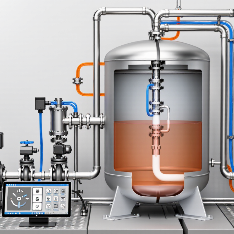
An automated tank filling system uses sensors, controls, and a pump or valve to keep a tank within a chosen level range. A level sensor measures the liquid, while a controller compares that reading with preset limits. When the level drops, the controller starts filling. At the upper limit, it stops the flow. Simple in principle. Not magic. A float switch may suit a basic water tank, while ultrasonic or pressure sensors can serve installations needing continuous level readings. The right choice depends on the liquid, tank shape, and operating conditions.
In practice, a system may include a control panel, shutoff valve, overflow protection, and an alarm for abnormal readings. Imagine a tank in a utility room: the sensor detects a low level, the valve opens, and a status light shows that filling is underway. Small details matter. Deposits, foam, or sensor misalignment can cause inaccurate readings, so inspection and testing should be part of routine care. During commissioning, operators should verify both start and stop points under real conditions. A sensor can drift over time. That is easy to overlook. A well-designed setup makes filling more consistent, but it still needs human oversight and maintenance.

Core Components and Operating Principles
An automated tank filling solution links a supply tank, transfer pump, flow meter, fill valve, sensors, and a programmable controller. The controller compares the measured level or delivered volume with a setpoint, then slows or stops flow. A high-high level switch can act as an independent cutoff. That backup matters.
Sensor choice depends on the liquid and vessel. Radar level measurement can suit many closed tanks, while load cells measure vessel weight directly. Viscous liquids, foam, turbulence, and residue can still distort readings. A tidy control diagram does not remove those realities. Verify readings against a known volume during commissioning, and check shutoff delay to prevent overshoot.
Automation is expanding across industry, though broad robot figures are not tank-filling performance data. The International Federation of Robotics reported 541,302 industrial robot installations in 2023, following 553,052 in 2022, in its World Robotics reports. These figures show the wider move toward automated production, not a guaranteed benefit for every filling line. For a sound design, specify compatible wetted materials, calibrated meters, clear alarm thresholds, and a safe manual stop. Keep records of calibration and test the cutoff routinely. One detail is often missed: filling accuracy depends on the whole system, including stable supply pressure and operator setup.
| Component or Design Choice | Operating Principle | Best-Fit Use | Key Selection Considerations | Typical Limitation |
|---|---|---|---|---|
| Batch measurement: load cells | Load cells under a vessel measure weight. The controller stops filling when the measured mass reaches the target, with allowance for material that continues flowing after shutoff. | Recipe-based batching, changing liquid densities, and applications where the target is specified by mass. | Check vessel support design, vibration, pipe forces, temperature effects, calibration access, and the required weighing range. | Mechanical forces and vibration can affect readings; installation and calibration quality matter. |
| Batch measurement: flow meter | The meter measures flow in the filling line, and the controller totals the measured flow until the preset volume or mass is reached. A shutoff valve or pump then stops delivery. | Repeatable transfers through a fixed pipework route, especially where the product and flow conditions are well defined. | Match meter technology to fluid conductivity, viscosity, temperature, pressure, flow range, and required hygienic or hazardous-area rating. | Meter performance depends on correct sizing, installation, product properties, and calibration. |
| Tank level measurement | A continuous level instrument measures the liquid surface or hydrostatic head. The control system uses the level signal to manage filling and prevent overfill. | Storage tanks, replenishment control, and processes where tank level—not a precisely measured batch quantity—is the primary control variable. | Consider foam, vapor, turbulence, tank geometry, density, sensor mounting, and whether contact with the liquid is acceptable. | Level alone does not directly measure transferred mass; tank shape and product conditions can affect interpretation. |
| Independent high-level protection | A separate high-level switch or approved overfill protection device detects a high level and initiates an independent alarm or shutdown action. | Recommended wherever an overfill could cause a spill, equipment damage, environmental release, or personnel hazard. | Determine the required safety function through a site risk assessment; verify device suitability, testing, and shutdown response. | A protective switch is not a substitute for correct operating controls, inspection, and proof testing. |
| Control system: PLC and HMI | A programmable logic controller reads instruments, runs the filling sequence, checks permissives, and commands pumps and valves. The human-machine interface displays status, alarms, and authorized settings. | Automated single-tank or multi-tank systems requiring repeatable sequences, alarm handling, and operator visibility. | Define I/O, communications, recipe controls, alarm behavior, access permissions, event records, and integration needs. | Control logic cannot compensate for unsuitable instruments or poorly defined operating procedures. |
| Final control element: valve or pump | A controller starts or stops a pump, actuates a valve, or adjusts a control valve to regulate flow. A fast-fill/slow-fill sequence can reduce overshoot in batch filling. | All automated filling systems; the choice depends on the source, required flow, fluid properties, and process layout. | Check wetted-material compatibility, pressure and flow ratings, leakage requirements, actuator type, and safe response on power loss. | Shutoff delay and liquid remaining in the line can cause overshoot unless accounted for. |
| Interlocks and permissives | Logic permits filling only when required conditions are satisfied, such as a valid destination, available capacity, and acceptable equipment status. Faults trigger a defined stop or alarm response. | Systems with multiple tanks, shared transfer lines, hazardous products, or a need to prevent incorrect routing. | Document each permissive, alarm, reset condition, and failure response; validate the sequence during commissioning. | Excessive or unclear interlocks can make operation confusing and encourage workarounds. |
| Recommended solution by application | For mass-based batches, use load-cell weighing with PLC control and independent overfill protection. For controlled in-line transfers, use a properly selected flow meter with totalizing control and independent overfill protection. Use level control for tank replenishment where a precise batch quantity is not the main requirement. | Choose according to whether the process needs mass batching, measured transfer, or inventory-level control. | Confirm the target quantity, fluid properties, required repeatability, process hazards, cleaning needs, and applicable local requirements before selecting equipment. | There is no single best arrangement for every tank; performance depends on the application, installation, calibration, and maintenance. |
Note: Instrument accuracy and system performance are application-specific. Verify equipment ratings, installation requirements, and safety functions against the fluid, process conditions, and applicable standards.
Automated tank filling systems generally use timed, volumetric, level-based, or gravimetric control.
Timed filling is simple: a valve opens for a set period. It suits stable liquids and repeatable conditions, but viscosity changes can shift the final quantity. Simple, but sensitive.
Flowmeter-based systems measure product moving through a pipe. Magnetic meters suit conductive liquids, while Coriolis meters measure mass flow and can handle changing density. They work well for frequent batches, though bubbles, vibration, and poor installation can affect readings.
Level-based systems use point switches or continuous sensors to stop filling at a set height. They are practical for large tanks, but foam and turbulence can mislead sensors.
Gravimetric filling uses load cells beneath a tank or vessel to track weight directly. It can be useful when volume changes with temperature or density matter.
OIML’s R 61 standard covers automatic gravimetric filling instruments and their metrological performance. The International Energy Agency’s Energy Efficiency 2023 report says industry accounts for about 37% of global energy use, underscoring the value of reducing avoidable process waste. That figure is not specific to filling.
And control choice alone will not fix a poorly maintained valve. Calibration, product behavior, and cleaning requirements deserve equal attention.
How to Evaluate Filling Solutions in 2026
Choosing an automated tank filling solution starts with the liquid, not the machine. Record its viscosity, temperature range, foaming behavior, and target fill tolerance. Then test the actual tank geometry: a narrow inlet or uneven floor can create splashing and inconsistent readings. The International Federation of Robotics reported 541,302 industrial robot installations worldwide in 2023. That figure signals broad automation adoption, but it does not prove a system will suit your process. Ask for measured accuracy across real operating conditions, not just a best-case demonstration.
Compare solutions using repeatability, changeover time, cleanability, and integration needs. Check whether sensors remain reliable when condensation, bubbles, or residue appear. The 2024 Deloitte Smart Manufacturing Survey found that 86% of surveyed manufacturers viewed smart manufacturing as a competitiveness driver over the following five years. Still, connected controls add little value if operators cannot troubleshoot them. That part is easy to overlook.
Tips: Run a short pilot with your own liquid and tank. Track fill variation, spills, downtime, and cleaning minutes per shift. Include maintenance and calibration costs in the comparison. A spreadsheet helps, though it will not capture every awkward changeover. Keep that limitation visible.
An automated tank-filling system should fit the process, not just the tank volume. Identify the liquid’s viscosity, temperature range, target fill level, and required filling rate. Water-like liquids may work well with a level sensor and shutoff valve. Foam, splashing, or changing liquid properties can cause inaccurate readings. Consider whether operators need batch records, alarms, or a manual override. Small details matter. Check that sensors and valves remain accessible when pipes are crowded.
Tips: Match the sensor to the liquid and tank shape. Ask how the system responds to a blocked inlet, power loss, or sensor fault. Test the setup with the actual liquid before full operation, if practical.
A clear specification helps suppliers recommend suitable equipment, but avoid choosing accuracy beyond what the process needs. That can add cost and maintenance without improving results. Review the expected flow rate against the supply pressure, and confirm the valve closes quickly enough to prevent overflow.
A neat drawing can still miss a troublesome detail, such as foam reaching a sensor before the liquid reaches its target level. Plan for calibration, cleaning, and routine inspection. Keep it simple, but leave room to adjust settings as production needs change.
Same Day Shipping
ISO Certified Production